Equipment Records
Create new Equipment records in Calibration Control (our Calibration Management Software) to identify, track and manage all data specifically related to the tool / test equipment.
The Edit Equipment dialog is a compact data record storing all related information of an item. Manage dates, maintain current status and location, attach files, print labels or worksheets, track transaction logs, and record all history of calibrations and maintenance in a single dialog.
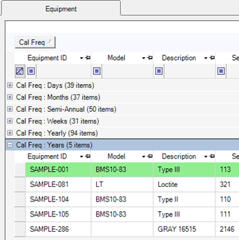
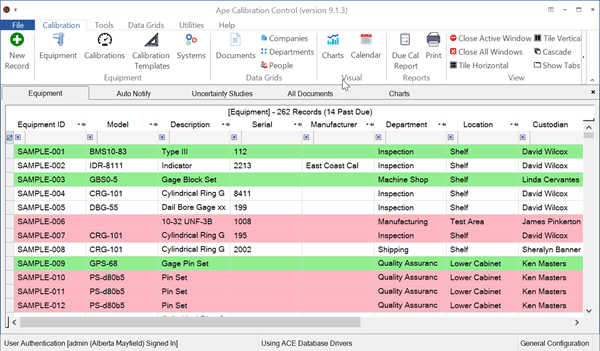
View Equipment Grid
Add New Equipment Record
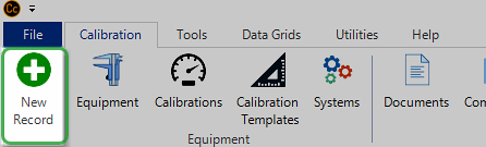
Use any of the following methods to create a new record of Equipment:
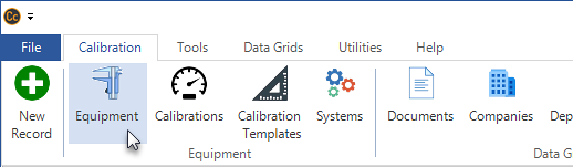
- By clicking on the green plus sign [+] New Record icon on the left side of the ribbon menu (above image)
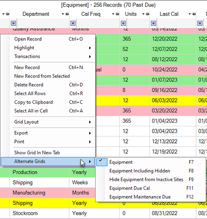
- By right-clicking within the grid and selecting New Record from the pop-up context menu
- By hitting [Ctrl+N] keys
- By double-clicking unpopulated gray area around the grid rows
Open Edit-Equipment Dialog
Double-click on a grid row as one method to open the Equipment record. The Edit-Equipment dialog fields are defined below. Rename and change any field label names to apply other terms that make more sense to your organization, (e.g., rename field label "Equipment ID" to "Asset Number" if desired.)

Equipment (Main) Tab
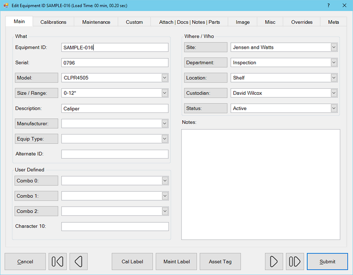
The Equipment (Main tab) fields of the Edit Equipment dialog are defined below. Note: If the field name* appears in a shaded clickable box, you can click directly the field name in order to quickly add a new data record to the corresponding combo-box (drop-down list) of available values.
- Equipment ID: The unique identification given to your own tools / test equipment and is often referred to as an Asset Number. This is the only required field to create a new Equipment record. Create custom number masks to set Equip ID to automatically increment.
- Serial Number: The unique identification the manufacturer gives their tools / test equipment. (You may periodically find that some manufacturers do not assign serial numbers or that the S/N label has fallen off.)
- Model*: The Model number of the tool / test equipment, usually assigned by the manufacturer.
- Size/Range*: The size or range of the tool / test equipment. All size/ranges are available in Codes.
- Description: The description of the tool Model number automatically reflects the chosen Model number's description field, if populated. Once the model is already selected, then the description field for this tool can be further edited.
- Manufacturer*: The manufacturer Company that made the equipment / tool. This field will also automatically set if an existing Model number is chosen and has a Manufacturing Company (as the Type) assigned.
- Equip Type*: A classification system developed by you. (Examples of Types include Caliper, 6" Caliper, Thermatron, Oven, etc.) This field will automatically set if an existing Model is chosen and has a Type field assigned.
- Alternate ID: This is a second ID field, the Equipment ID being the first. Use this field to record a customer's Equipment ID, or a company Asset number, if it is not the same as the Equipment ID.
- Site*: Company field for a geographical site or company for this tool.
- Department*: The department in the organization where the tool is currently used or located.
- Location*: The primary (or physical) location, such as within a department where the tool is currently located. This could be a designated work area or even a specific engineer's desk.
- Location* 2: (Recently added in version 9.7) A secondary location, such as within a department where the tool is currently located. This could be a designated work area or even a specific engineer's desk.
- Custodian*: The individual who has custody or possession of this tool.
- Status*: The current status of the tool / test equipment (e.g., Active, Checked Out, Lost, Removed, In Calibration, etc). Create custom Equip Status Codes. Refer to archiving or Hiding Equipment by Status and using the Status Change feature.
- Notes: Enter short text notes for any purpose.
- Combos 0*, 1*, 2*: Three custom combo-boxes are added (since v9.6) so users can create their own drop-down lists for equipment categories and attributes. Edit the combo-box records in the drop-down lists by going to its group in the Codes grid.
- Character 10: A custom character field shows in the Main tab of the Equipment record. All other custom fields are in the Custom tab of the Edit Equipment dialog. Rename field label names, especially user defined custom fields, to something else that makes more sense to you.
Watch a Video for the newly-added User Defined fields:
Calibrations Tab
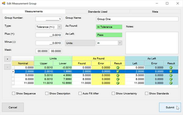
Use the Calibrations tab of the Edit Equipment dialog to create calibration history for this tool. Whether or not it includes measurements, click the green [+] button to record a new Calibration Event for this tool with correct dates and document the final results.
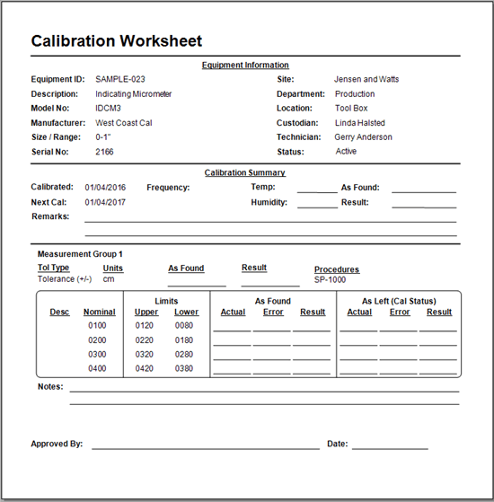
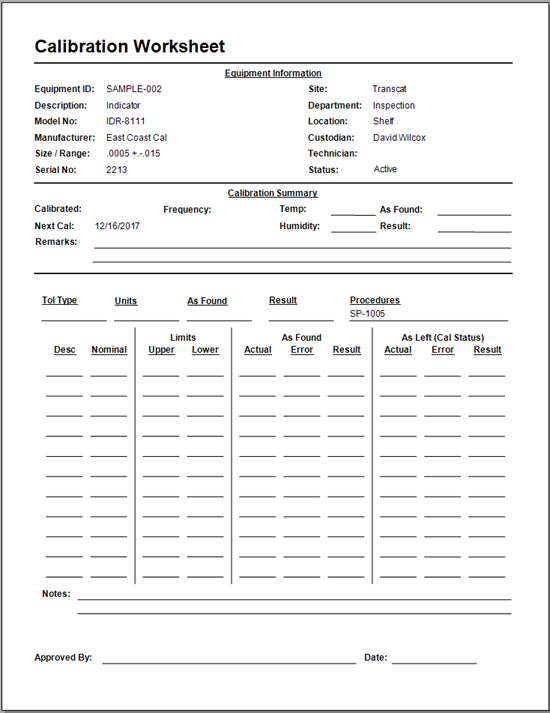
Click the [Print Certificate] or [Print Worksheet] buttons for a print-preview or (if desired) straight to your default printer.
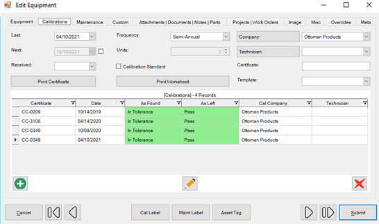
All Calibrations tab fields of the Edit-Equipment dialog are defined below:
- [Calibration] Last: The date of the last calibration is set automatically when entering a new Calibration Event with a Status of Pass. The Calibration Last date can be set manually, which automatically updates the Calibration Next field based on the value of the Frequency field.
- [Calibration] Next: The date of the next calibration is calculated automatically when entering a new passing calibration event or when manually updating the Calibration Last field. In either situation, the next calibration date is calculated based on the chosen Frequency and Units.
- Override Next [Checkbox]: Manually extend or otherwise override the Calibration Next date by checking the box to the right of the Calibration Next field.
- Received [for Calibration]: The date when equipment was received for Calibration. Refer to the Status Change feature to automatically set and clear this date field.
- Frequency / Units: The required frequency between calibrations, like yearly or semi-annual. If choosing a frequency that requires a unit multiplier (e.g., weeks, days, or months), the Units field will enable to adjust the number of units (weeks, days, or months, etc.). The 'Month of' and 'Week of' frequencies set a general due date of an entire month or week.
- Calibration Standard [check box]: Check this box if the current equipment is used as a Calibration Standard or master test gage used to perform calibrations of any other equipment.
- Company*: The organization (Calibration Company) that regularly calibrates this instrument. This is a useful field when wanting to create a report of all the equipment due in a given period for a specific calibration resource.
- Technician*: The person who normally calibrates this equipment.
- Certificate: Number of the Certificate issued by the organization responsible for the last calibration event. Used primarily to aid in traceability back to a national measurement standard, especially if this equipment is a Calibration/Test Standard. Note how a certificate number can be referenced...
- Cert. No. Ref: Determine how your Certificate Number field is referenced when the Standard Equipment is linked in a Calibration Measurement Group and prints a Cert number on a Certificate. Change settings by going in the Options dialog / Advanced tab / Calibrations tab.
- Template: Select a custom Template when creating a new Calibration Event. (By default, the most recent calibration record will serve as a calibration template for future calibration records of this tool.)
Maintenance Tab
Use the Maintenance panel grid of the dialog to create, link, and track Maintenance results tied to an Equipment record. Maintenance Notes are formatted as long text notes for recording results of routine inspection cycles. Create a new Maintenance Cycle Note by selecting the green [+] symbol at the bottom of the dialog.
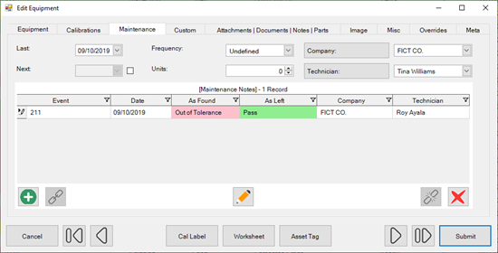
Additionally, monitor Equipment with Maintenance Due with grid colors and/or view Equipment Maintenance Due in the context menu of the Equipment grid (F12).
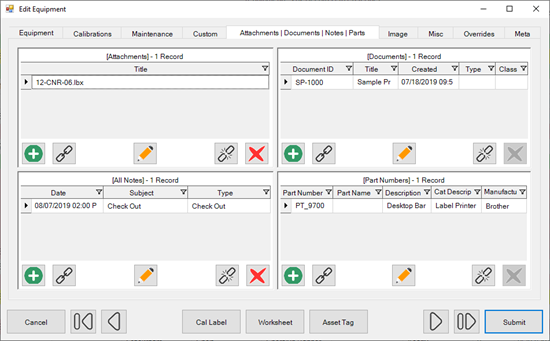
Attachments|Documents|Notes|Parts Tab
Use these panel grids to add, link, and edit the Attachments, Documents, Notes, and Part Numbers records related to an Equipment record.
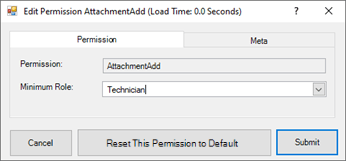
- Attachments: Attach a Certificate provided by an external calibration company, Cal Worksheets, or link other existing Attachment records to this Equipment record. (Note: Attachments link separately to the Calibration Event(s) for the Equipment record.)
- Documents: Attach Document records of Procedures to the Equipment record. Documents / procedures linked to the most recent Calibration Event of this Equipment are linked to its future calibration records.
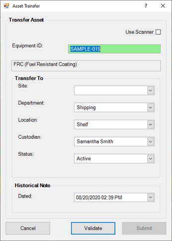
- Notes: Link existing Note records to this Equipment record or manually add a new Note. All the transaction activity of Check Out, Asset Transfers, and Status Changes for this Equipment is auto-recorded in the Notes tab. These Notes can be opened and further edited.
- Part Numbers: Link more Part Number records to this Equipment record, or link more Equipment from within the Part Number record.
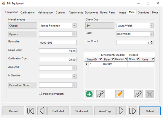
Miscellaneous Tab
The Misc tab contains groups of data to help organize information related to the Equipment record.
-
Miscellaneous Group:
- Owner*: The Owner (Person field) of this tool / equipment, if not the organization. A [Personal Property] check box is also available.
- System*: View or assign an Equipment System to which this Equipment belongs.
- Barcodes*: Additional or custom barcodes that may already be provided on the tool / equipment. This field is especially useful if printing new barcode labels are unnecessary, and Calibration Control can recognize the custom barcode labels already affixed to this tool / equipment.
- Equip Cost: Record the purchase price of this Equipment.
- Calibration Cost: Record the general calibration cost for this tool. The specific costs and calibration time spent is stored in the Calibration Event record (Standards | Misc tab).
- Acquired: Record the Acquisition date of this Equipment.
- In Service: Record the In-Service date for this Equipment.
- Procedure: Link a Procedural Group from the combo-box list to tie to this Equipment for procedural steps in calibration worksheets.
-
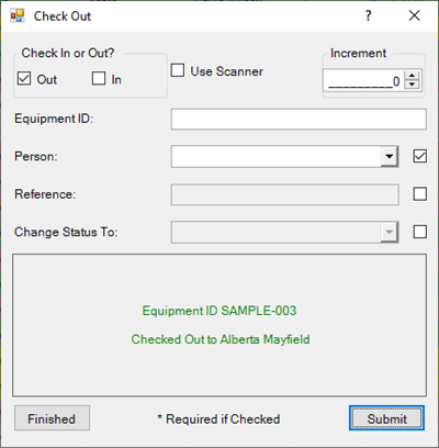
Check Out Group: Using the
Check In/Out dialog
automatically populates the following fields:
- By*: The Checked Out By field shows the person who has checked out the Equipment, if assigned.
- Date: The Checked Out Date field shows the most recent date this Equipment was checked out, and only populates if it is currently checked out. When not checked out, this field is blank.
- Use Count: Number of times this Equipment was checked out since its last Calibration date.
- Uncertainty Studies panel grid allows you to link a Measurement Uncertainty Study group to this Equipment record.
More Tabs in the Equipment Dialog
There are more tabs within the Edit Equipment dialog to help organize related data for the open Equipment record. . .
- Custom tab contains extra fields available in text, date, number, and checkbox format to easily rename and use for whatever needed.
- Image tab allows you to select a picture and view one main graphic image that represents that specific Equipment record.
- Overrides tab contains the selections for optional label and report overrides. Default labels and reports are defined at a global (application) level in the Options dialog, while the override selections for Labels and Reports applies for this specific Equipment record.
- Projects & Work Orders tab contains a panel grid of the Work Orders or Projects to which this equipment record has been linked. This is hidden by default. Show this tab by going to Feature Visibility in program Options.
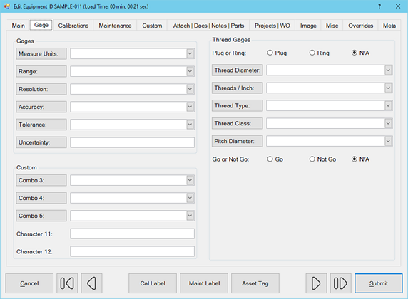
- Gages tab, recently added, is hidden by default. Show the Gages tab by going to Feature Visibility in program Options.
- Meta tab is a READ-ONLY information tab used as a reference to view which user created the record and which user was the last to edit it, including the dates and times these occurred.
Last Updated: 18 June 2024